+ Reply to Thread
Page 6 of 16 FirstFirst ... 45678 ... LastLast
Results 51 to 60 of 156

Thread: Oxford Crystal Reference restoration

  1. #51
    Join Date: Nov 2008

    Location: North Down /Northern Ireland/ UK

    Posts: 19,484
    I'm Neil.

    Default

    The problem was that they expanded their range too quickly by adding a cheaper turntable (about £800 ish) and a range of electronics (which were not imho very good or well built), then the recession of the early 90's hit and bamb they disappeared.

    I don't remember the whole story, it was along time ago and at the time the dealer I worked for did not sell lots of their kit, a few Oxfords (3 or 4), a Cyrstalette and a few of the cheaper TTs. I can't remember if we sold any of the amplifiers.


    Regards D S D L
    Regards Neil

  2. #52
    Join Date: Jan 2009

    Location: Deleted

    Posts: 6,585
    I'm Deleted.

    Default

    Can we have pics of the bearing all in bits please - if possible?
    Account Deleted

  3. #53
    Join Date: Jan 2008

    Location: Winchester, Hampshire

    Posts: 309
    I'm Steve.

    Default

    Peter

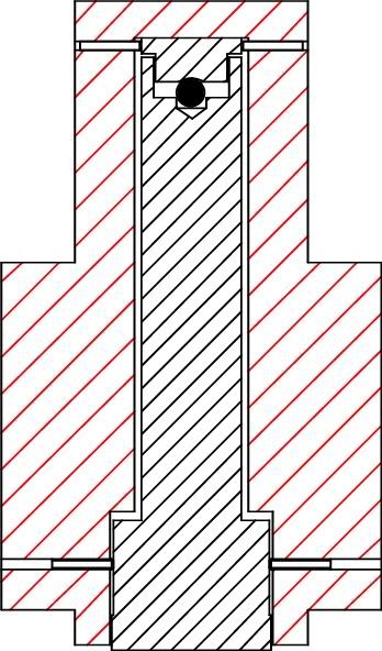
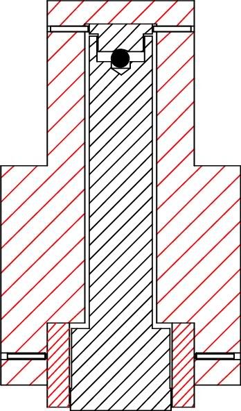
    From your descrription and the photo of the underside of the phosphur bronze platter, an easy workaround may be to just remove the Allen bolts and locate one of the empty holes over the raised pin on the bearing housing lip to achieve a flush fit.

    By carefully listening (once everything is up and running) you could rotate the platter to align each of the bolt holes in turn to see whether there was any sonic difference and if so which was the preferred position and then mark it for future reference.

    The bolts could then be replaced and aligned and listening tests would again indicate which was the preferred option - bolts or no bolts.

    That way, you would not have irrevocably altered the design of your deck by filing down/removing the pin.

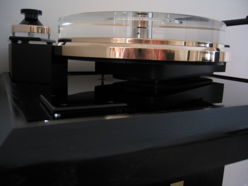
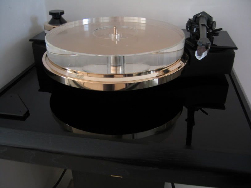
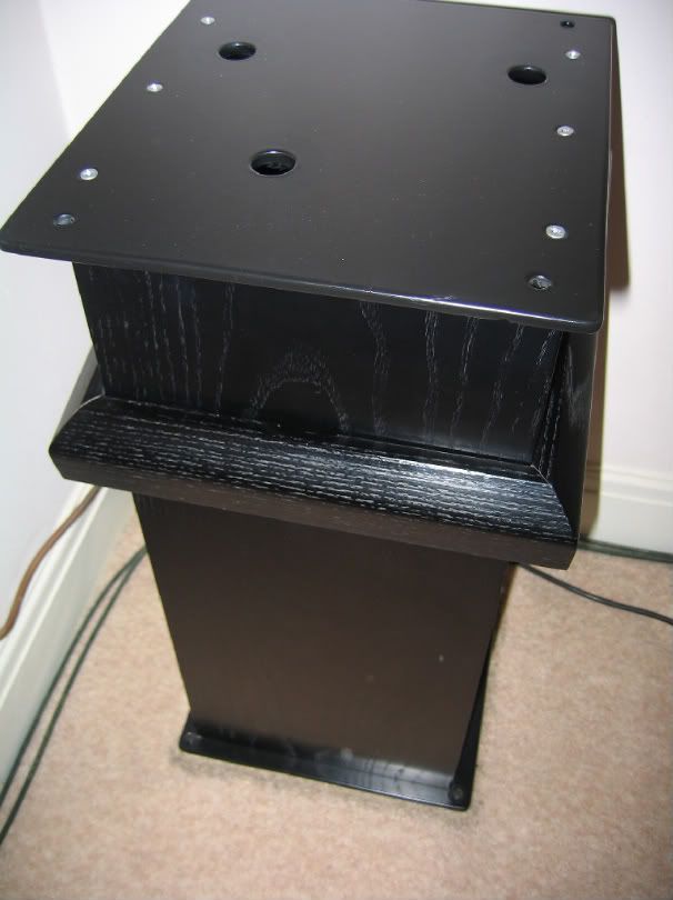
    Unfortunately I didn't take any photos of the disassembled bearing when the Oxford was in my posession. The only other pics I have are these which show the bearing housing and sorbothane spacer underneath the detachable spindle visible through the clear acrylic upper platter. The ubiquitous black ash finish of the 80's does look rather dated now!


    With SMEV and Koetsu Rosewood Signature mc cartridge.


    Another nice aesthetic touch was the veneered 'skirt' which could be raised up the stand and rested on the rear lip below the DIN socketry to allow the four lock nut spikes to be levelled at the base of the stand. The skirt could then be slid back down to hide the spikes.


    Another view of the component parts showing the exemplary engineering and finish.

    Steve.

    My System:- dCS Vivaldi Transport + dCS Vivaldi Apex DAC + dCS Vivaldi Master Word Clock + dCS Vivaldi Upsampler Plus, Aurender N20 Music Server/Streamer, TW Raven One tt/Graham Phantom II/Transfiguration Orpheus L & Audio Technica ART20 mc's, Whest Titan Pro, D'Agostino Momentum HD pre/S250 MxV power amp, TAD CR-1 MKII loudspeakers, REL Gibraltar G2 subs, Coherent Systems BD Mains, interconnects & speaker cables, Sablon Audo EVO USB cable, Tellurium Q Ultra Silver power cords, Ziro Disclosure & Vertex Roraima Hi-Rez power cords + Furutech FI connectors, Stillpoints ESS racks/component stands, Vertex Aletheia PSU2 balanced power supply, Coherent Systems RTZ3 ground box + CR/BD cables, Acoustica Applicata DaaD room treatment, Mutec Ref10 SE-120.

  4. #54
    Join Date: Aug 2010

    Location: Peterborough, UK

    Posts: 97

    Default

    Quote Originally Posted by YNWaN View Post
    Can we have pics of the bearing all in bits please - if possible?
    Coming soon on THIS thread!


    But first, a word from my sponsor:


  5. #55
    Join Date: Jan 2009

    Location: Deleted

    Posts: 6,585
    I'm Deleted.

    Default

    You tease .
    Account Deleted

  6. #56
    Join Date: Jun 2010

    Location: Southampton

    Posts: 1,620
    I'm drunk.


  7. #57
    Join Date: Aug 2010

    Location: Peterborough, UK

    Posts: 97

    Default

    Just to round off the discussion about the bolts, another picture.


    Today I will take this apart


    but first I'm going to remove the armboard . Good time to apologise upfront for the quality of some of the pictures. I am more concerned with what I'm doing than photographing what I'm doing, I'll be more careful next time.


    So with the armboard off we are left with this. There are 8 bolts holding the sandwich together.


    Inspection reveals another set of holes at the bottom of the bearing housing


    I want to seperate the bearing from the sub-chassis so I don't damage the latter. Underneath the S/C the bearing is held on by a brass ring. it won't turn by hand but there is a thread that we can get at


    This means a trip to the batcave:


    This bolt happens to fit in the thread, It's came with my flatscreen wall mounting kit.


    People of nervous disposition please look away now.

    I am holding the bolt in the vice, this may scratch the S/C. Hold onto the S/C and... HRRRRRRRRRG, oops


    This is going to be more difficult than I imagined:


    Interlude while I check the fixing of my TV.

    Ok back in the kitchen now. Put down kitchen paper in case the ball goes walkabout, thanks for the tip Steve.


    This is it folks I will skip the comments on the next few photos while I look up some terminology. I'm a brain-surgeon not a shipbuilder as a brain-surgeon would say.


    Hold your horses, more photos are coming.

  8. #58
    Join Date: Aug 2010

    Location: Peterborough, UK

    Posts: 97

    Default

    It looks like there was gap at the bottom end housing on one side, judging from the oil.


    I think this is the journal?


    I am going to tease out the ball before I lose it


    I think we need an oil change


    Here is the ball


    Mother and child


    Going to clean the ball seat


    Like so


    Put the ball back for now


    I am interested in where the lower bearing sleeve locates, here?


    or here?


    Its the bottom one, it seems a good fit as the oil doesn't leak


    Now I shall investigate the thrust plate


    First I shall clean it to get a clear shot


    Here we can see where the top grub screws engage, I am going to unscrew one so I can remove the plate


    It won't come out so I will get at it with tweezers


    Got it


    It is flat on the other side


    It would go sorta like this


    Does it look worn? Rumble was never an issue for me.


    This is where it went.


    That the end of this slideshow, Accepting requests before I bag everything.
    Last edited by peter; 15-08-2010 at 14:08. Reason: Missing photo

  9. #59
    Join Date: Jan 2009

    Location: Deleted

    Posts: 6,585
    I'm Deleted.

    Default

    Hmm..interesting (very, very interesting in fact and huge thanks for the excellent pictures).

    So, how novel. The bearing is supposed to be self aligning by the look of it. At the base it is centred by the brass/bronze (but looks like brass to me) collar of the outer bearing and at the top the ball bearing rests in the little hemispherical divot (the position of which can, unfortunately, be adjusted).

    Something like this:

    Last edited by YNWaN; 15-08-2010 at 15:17.
    Account Deleted

  10. #60
    Join Date: Jan 2009

    Location: Deleted

    Posts: 6,585
    I'm Deleted.

    Default

    Ah no, I see - the three lower grub screws look like they could be retaining a bronze inner shell that forms the actual bearing surface - that would make more sense.

    More like this:

    Last edited by YNWaN; 15-08-2010 at 15:31.
    Account Deleted

+ Reply to Thread
Page 6 of 16 FirstFirst ... 45678 ... LastLast

Posting Permissions

  • You may not post new threads
  • You may not post replies
  • You may not post attachments
  • You may not edit your posts
  •